DDPI Rotation Stage Development
Use this page for sharing information and tracking progress on the development of the procedures and protocols for the new DDPI artificial eye rotation stage from PI.
Contents
Procedures for using PI Rotation Stage
These procedures explain how to install the drivers and software, how to set up the stage, and how to get started programming the stage using the MATLAB functions the Ruei developed.
Procedures, rev. 1 (4/2/21 by Ben Moon)
Matlab control scrip can also be found in Gitlab repo.
rotational stage Gitlab repo
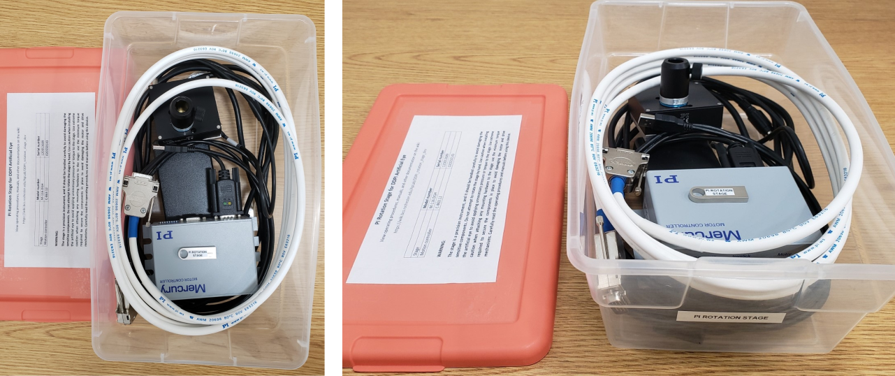
The photos below show the PI rotation stage and all associated hardware in the designated storage box. 
Minimum incremental motion
The minimum incremental motion for the stage is:
0.001451 degrees (which is equivalent to: 0.08706 arcmin = 5.224 arcsec = 25.32 microradians)
This value was found by entering the minimum incremental motion parameter from the datasheet (25 microradians = 0.001432 degrees) into the step size field on the control interface in PIMikroMove. The step size was rounded by the software to 0.001451 degrees, which is the actual minimum step size for the stage.
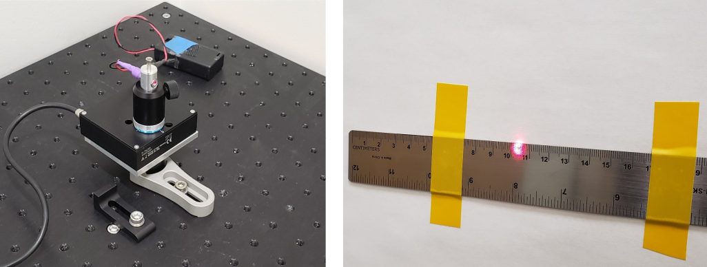
This minimum incremental motion was validated by placing the stage's rotation axis 4.000 meters from the observation plane and installing the red laser pointer in the post holder attached to the stage. At a distance of 4.000 meters, the minimum incremental motion of 0.001451 degrees corresponds to 0.1013 mm. A ruler with 1 mm rulings was taped to the wall at the observation plane and was used to measure the movement of the beam. Due to the beam diameter of about 7 mm, it was difficult to observe any motion from the minimum incremental motion of 0.001451 degrees. Therefore, the stage was moved by the minimum incremental motion 10 times. The observed beam displacement was 1.0 mm, which corresponds to the expected motion of 1.013 mm.
A MATLAB script was written to move the stage in 100 steps of the minimum incremental motion, waiting 0.25 seconds between each step. When executed, the beam moved by 10.1 mm as measured by the ruler on the wall. This corresponds to the expected motion of 10.13 mm. These tests demonstrate that the stage is capable of making accurate, controlled movements of less than 1/10 of an arcmin. The test setup is shown in the pictures below. This test was conducted by Ben Moon on 4/7/21.

Additional Documentation
Manual and datasheet for rotation stage
Manual and datasheet for driver box
C-863 manual
C-863 datasheet
C-863 installation files - copy of files on CD that came with the system (.iso file format). To install the software on a Windows computer, download the .iso file, right click on the file and select mount, and then run PISoftwareSuite.exe.
Quote from PI for this system
Quote for stage, driver, and cables
Future development ideas and plans
In talking with Scott Giancola (ScottG@pi-usa.us) from PI (the sales director who helped us decide on the right configuration for our application), we determined that the most reliable way to drive a low-frequency sinusoid is using the analog input for the joypad controller. The document below explains how they (some engineers from PI) accomplished this task for one of their customers. This is something that we will want to explore in the future, after we get the system running with the digital interface. Using this alternative arrangement would allow us to drive the system using an analog function generator.
Stage control through analog input
CAD files for various parts
CAD files are available here
Verifying rotation angles
Rotation angles were measured in 1 degree increments over a range from -10 degrees to 10 degrees to verify that the stage was going to the angles we were commanding. This report shows how the test was set up and the results we obtained. It demonstrates that the stage rotates to the commanded position with a high degree of accuracy.
