PCB for photodiode
Quick Description
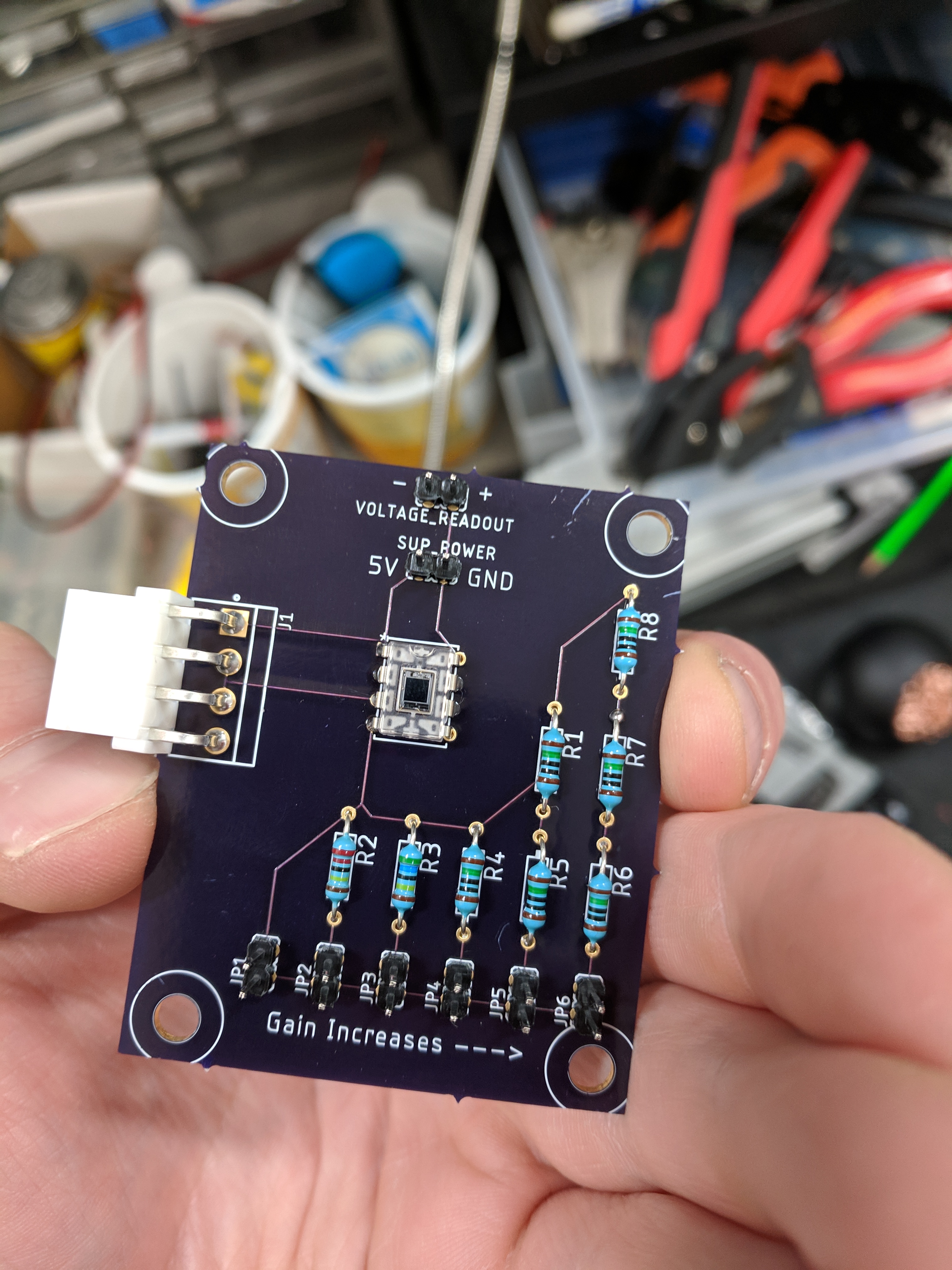
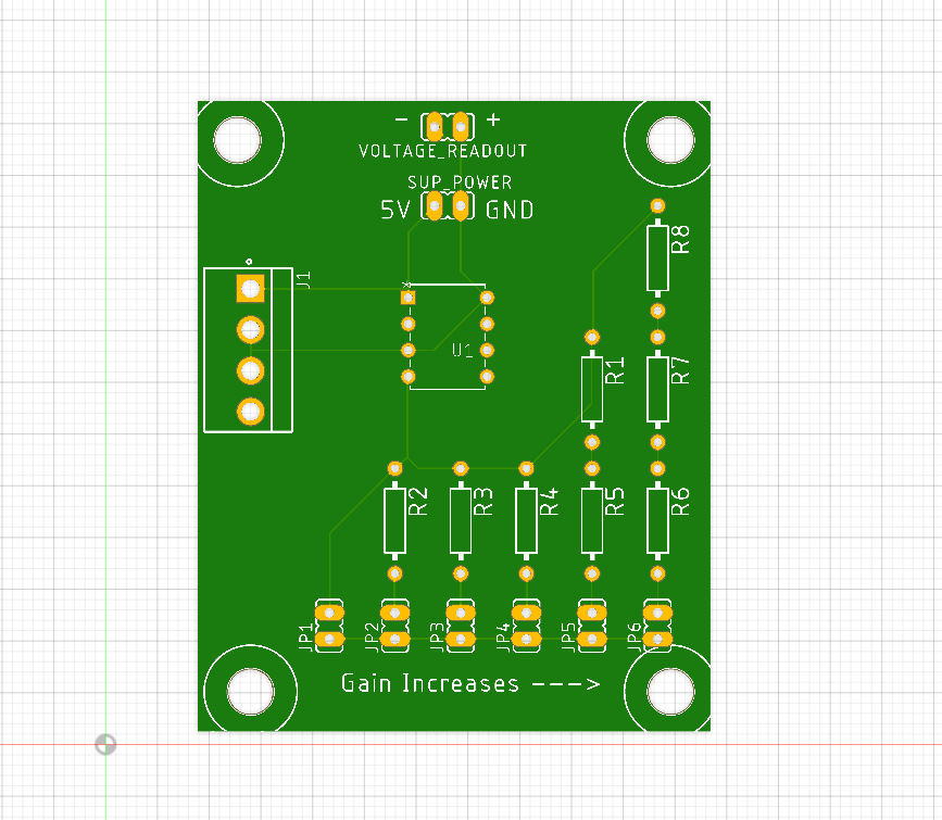
This Circuit uses a set of parallel circuits each with varying resistance to adjust the gain of our photodiode. The Gain can be selected using a jumper placed in series with the desired resistance to close the circuit.
The exact exact gain response is not known but is frequency dependent.
The resistances of each gain settings (not counting the internal op-amp resistor of 10MOhm):
- 0 Ohm (lowest gain)
- 2.2 MOhm
- 5.7 MOhm
- 10 MOhm
- 20 MOhm
- 30 MOhm (highest Gain)


Components
Photodiode/amp datasheet
DPI Cable
The function of each wire in the DPI cable is as follows:
- WHITE: signal
- RED: 5V
- GREEN: GND
- BLACK: NOT CONNECTED
the wire's metalic case shielding should be connected to GND!
Molex Cable
- The function of each wire in the molex board connector is as follows (little weird due to a mixup in board layout)
- YELLOW: 5V (connect to red in DPI cable)
- WHITE: GND (connect to green in DPI cable)
- BLACK: GND (connect to DPI case shielding)
- RED: SIGNAL (connect to white in DPI cable)
Designs
Ciruit
aplab_photodiode-board_layout.brd
aplab_photodiode-schematic.sch
